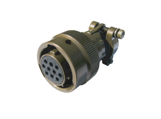
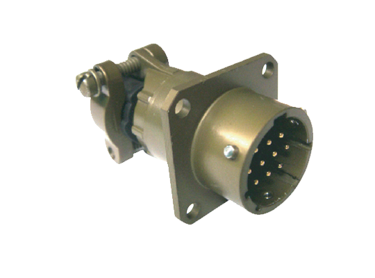
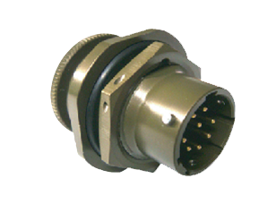
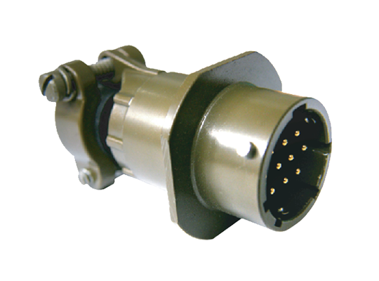
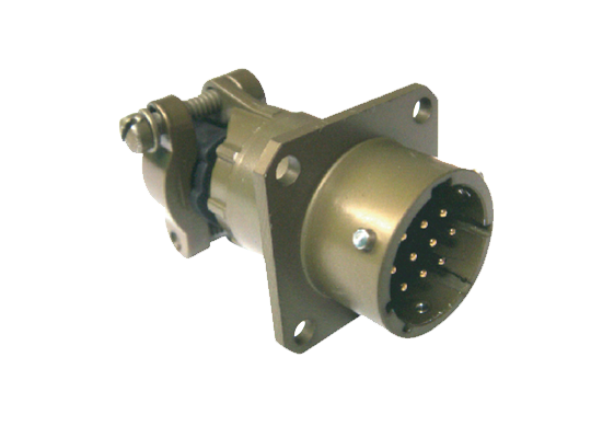
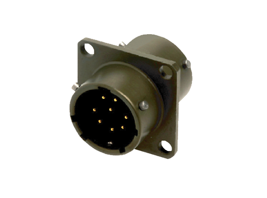
YJ 26482 시리즈 1 커넥터
26482 시리즈 커넥터는 소형크기의 구조에 고밀도의 접점 배열을 갖춘 커넥터로서 전기,기계적 성능 및 내환경 특성이 우수하여, 주로 고성능 접속솔루션이 필요한 군용통신 장비 및 산업용 장비등에 사용되고 있슴니다. 본 커넥터는 몸체에 5개소의 안내키 (Guide Key)와 베이오넷(Bayonet)결합방식을 채택하고 있어 결합이 매우 신속하게 이루어 지며 신뢰성이 매우 높은 접속을 제공하는 특징이 있습니다. 용진일렉콤은 오랜기간 축적된 콘넥터 제조경험을 통하여 다양한 26482 제품을 생산공급하고 있으며,고객이 요구하는 특별사양에도 신속히 대응을 하고 있습니다.
제품특징
- 소형화된 몸체에 고밀도 접점 배열을 갖춘 고성능 커넥터임
- Bayonet coupling 방식을 채용하여, 조립시공이 매우 신속 간편함
- 극한 사용조건에서 생존가능한 내환경특성을 보유
- 금도금 도체 및 전선과 연결시 납땜방식 채택
- 다양한 절연체 배열 및 도체규격 (#20 to #12) 제공
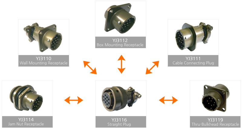
표준접속 가이드
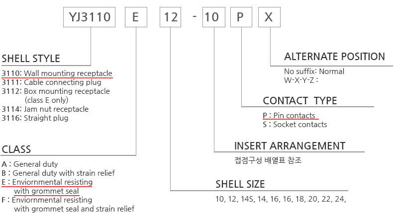
품명약호 및 주문 가이드
제품기술정보
Materials & Finish
| Materials | Finish | |
| Shell | Aluminum alloy | Olive drab chromate coating over cadmium or Zinc plating |
| Contact | Copper alloy | Gold plating |
| Insulation | Resilient Synthetic Rubber | |
Electrical Service Data
| Service rating | Operating Voltage | Test Voltage AC(rms),60cps | ||||
| AC | DC | Sea level | 50,000(ft) | 70,000(ft) | 110,000(ft) | |
| Ⅰ | 600 | 850 | 1,500 | 500 | 375 | 200 |
| Ⅱ | 1,000 | 1,275 | 2,300 | 750 | 500 | 200 |
| Contact Size | AWG Size | Max. Test Current (A) | Potential drop mV at 25℃ (Max.) | Dielectric O.D Limits (mm) | |
| Min. | Max. | ||||
| #20 | #24, 22, 20 | 7.5 | 55 | 1.52 | 2.11 |
| #16 | #20,18,16 | 13 | 49 | 1.68 | 2.77 |
| #12 | #12,14 | 20 | 42 | 2.46 | 3.61 |
| Insulation resistance | 5,000MΩ, min. (at 25ºC) |
| Temperature range | -55ºC to 125ºC |
| Durability | 500cycles connection / disconnection |
주) 본 기술정보는 해당제품의 대표값을 제시하고 있으며, 보다 자세한 내용은 당사 기술부서에 문의 바랍니다.
접점구성배열

Shell Size 8
| Insert Arrangement | 8-2 | 8-3 | 8-4 | 8-33 |
| Front face of pin inserts |  |
 |
 |
 |
| Service Rating | 1 | 1 | 1 | 1 |
| Number of Contacts | 2 | 3 | 4 | 3 |
| Contact Size | 20 | 20 | 20 | 20 |
Shell Size 10
| Insert Arrangement | 10-6 | 10-98 |
| Front face of pin inserts |  |
 |
| Service Rating | 1 | 1 |
| Number of Contacts | 6 | 6 |
| Contact Size | 20 | 20 |
Shell Size 12
| Insert Arrangement | 12-3 | 12-8 | 12-10 |
| Front face of pin inserts |  |
 |
 |
| Service Rating | II | I | I |
| Number of Contacts | 3 | 8 | 10 |
| Contact Size | 16 | 20 | 20 |
Shell Size 14
| Insert Arrangement | 14-5 | 14-12 | 14-15 | 14-18 | 14-19 | ||
| Front face of pin inserts |  |
 |
 |
 |
 |
||
| Service Rating | II | I | I | I | I | ||
| Number of Contacts | 5 | 8 | 4 | 14 | 1 | 18 | 19 |
| Contact Size | 16 | 20 | 16 | 20 | 16 | 20 | 20 |
Shell Size 16
| Insert Arrangement | 16-8 | 16-23 | 16-26 | |
| Front face of pin inserts |  |
 |
 |
|
| Service Rating | II | I | I | |
| Number of Contacts | 8 | 22 | 1 | 26 |
| Contact Size | 16 | 20 | 16 | 20 |
Shell Size 18
| Insert Arrangement | 18-11 | 18-30 | 18-32 | |
| Front face of pin inserts |  |
 |
 |
|
| Service Rating | II | I | I | |
| Number of Contacts | 11 | 29 | 1 | 32 |
| Contact Size | 16 | 20 | 16 | 20 |
Shell Size 20
| Insert Arrangement | 20-16 | 20-39 | 20-41 | |
| Front face of pin inserts |  |
 |
 |
|
| Service Rating | II | I | I | |
| Number of Contacts | 16 | 37 | 2 | 41 |
| Contact Size | 16 | 20 | 16 | 20 |
Shell Size 22
| Insert Arrangement | 22-12 | 22-21 | 22-32 | 22-41 | 22-55 | |
| Front face of pin inserts |  |
 |
 |
 |
 |
|
| Service Rating | I | II | I | I | I | |
| Number of Contacts | 12 | 21 | 32 | 27 | 14 | 55 |
| Contact Size | 12 | 16 | 20 | 20 | 16 | 20 |
Shell Size 24
| Insert Arrangement | 24-61 |
| Front face of pin inserts | 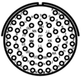 |
| Service Rating | I |
| Number of Contacts | 61 |
| Contact Size | 20 |
주) 본 란에 표시되지 않은 접점배열이 필요하신 경우 본사에 문의하여 주시기 바랍니다.

